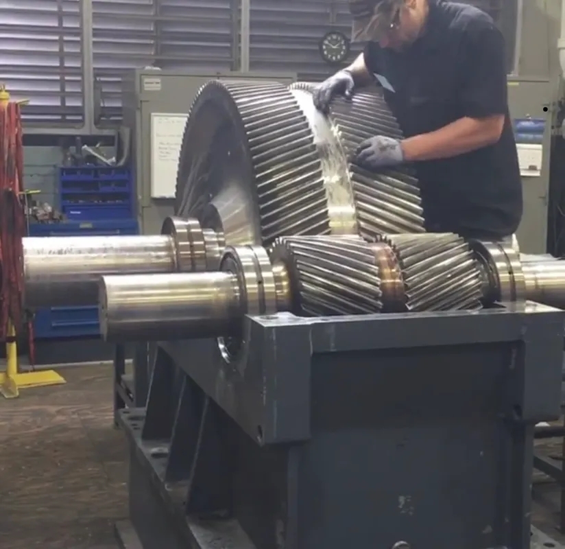
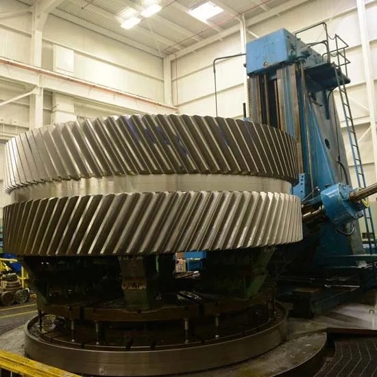
Gear Tooth Geometry Measurement

How is the involute profile of a gear tooth measured?

The involute profile of a gear tooth is typically measured using a gear tooth vernier caliper or a gear tooth micrometer. These specialized tools allow for precise measurements of the tooth profile, including the addendum, dedendum, and tooth thickness. By accurately measuring the involute profile, manufacturers can ensure proper gear meshing and smooth operation of the gear system.
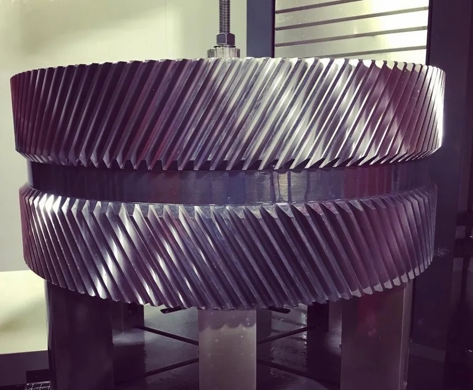
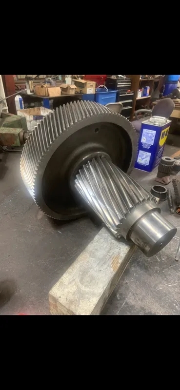
How is the involute profile of a gear tooth measured?

What equipment is commonly used to measure the pressure angle of gear teeth?

The pressure angle of gear teeth is commonly measured using a gear tooth profile projector or a gear tooth profile tester. These instruments provide a visual representation of the gear tooth profile, allowing for the accurate measurement of the pressure angle. By measuring the pressure angle, engineers can ensure that the gears will mesh correctly and transmit power efficiently.

How is the involute profile of a gear tooth measured?

How to grade operators in a factory and Why

Grading of the operators is categorizing or grouping the operators according to the various factors which is essential to do the job. In this article we will be discussing on how to grade operators along with the factors to be considered. So, stay tuned… We are explaining everything with practical examples. Before moving to our […] The post How to grade operators in a factory and Why appeared first on Know Industrial Engineering.

Posted by on 2024-03-07

Manpower calculation using takt time

In this article we will discuss and learn manpower calculation using takt time. This method is very simple and quicker, if we know takt time. The post Manpower calculation using takt time appeared first on Know Industrial Engineering.

Posted by on 2022-04-02

How to calculate headcount required in Excel

Optimum allocation of resources is the key to the success of every business or manufacturing. So, every business owner should know how to calculate headcount required in Excel. Also, Excel is most popular software and is easy to learn. In this article we learn how to calculate headcount required using Microsoft Excel and also you […] The post How to calculate headcount required in Excel appeared first on Know Industrial Engineering.

Posted by on 2022-03-28

Load Chart – For Scheduling, Monitoring and Tracing of production

If you have thought about how to optimize the production of low volume products, which requires highly skilled operators or costly machines, you might end up search with load chart. So read on to get a complete understanding on this topic. Load chart is a tool for scheduling, monitoring and tracing of production. You will […] The post Load Chart – For Scheduling, Monitoring and Tracing of production appeared first on Know Industrial Engineering.

Posted by on 2022-01-11

How to do capacity analysis for manufacturing

In this article we will discuss basics of capacity analysis. After reading this article you will be able to do capacity analysis for a manufacturing plant. I got a request in for uploading this article in the page, ‘request an article’. Hence this article. Ok lets move forward. What is capacity Capacity means ability to […] The post How to do capacity analysis for manufacturing appeared first on Know Industrial Engineering.

Posted by on 2021-10-10

How is the pitch diameter of a gear tooth typically measured?

The pitch diameter of a gear tooth is typically measured using a gear tooth caliper or a gear tooth micrometer. These tools allow for precise measurements of the distance between the gear teeth, which is essential for determining the gear ratio and ensuring proper gear meshing. By accurately measuring the pitch diameter, manufacturers can produce gears that operate smoothly and efficiently.

Specialized Industrial Gear Repair and Maintenance Solutions and Equipment

Gear Tooth Surface Treatment

How is the pitch diameter of a gear tooth typically measured?

What is the significance of measuring the addendum and dedendum of gear teeth?

Measuring the addendum and dedendum of gear teeth is significant because it helps ensure proper gear meshing and prevents interference between the gear teeth. The addendum is the distance from the pitch circle to the top of the gear tooth, while the dedendum is the distance from the pitch circle to the bottom of the gear tooth. By measuring these dimensions, engineers can design gears that operate smoothly and transmit power efficiently.

How are the tooth thickness and clearance of gear teeth measured?

The tooth thickness and clearance of gear teeth are typically measured using a gear tooth thickness gauge or a gear tooth clearance gauge. These tools allow for precise measurements of the space between gear teeth, which is crucial for ensuring proper gear meshing and preventing interference. By accurately measuring the tooth thickness and clearance, manufacturers can produce gears that operate smoothly and quietly.

How are the tooth thickness and clearance of gear teeth measured?
What methods are used to measure the root fillet radius of gear teeth?

The root fillet radius of gear teeth is often measured using a gear tooth profile projector or a gear tooth profile tester. These instruments provide a visual representation of the gear tooth profile, allowing for the accurate measurement of the root fillet radius. By measuring this dimension, engineers can ensure that the gear teeth have the necessary strength and durability to withstand the forces of operation.

How is the backlash of gear teeth typically measured and controlled?

The backlash of gear teeth is typically measured using a gear tooth backlash gauge or a gear tooth backlash tester. These tools allow for precise measurements of the clearance between mating gear teeth, which is essential for preventing binding and ensuring smooth operation. By measuring and controlling the backlash, manufacturers can produce gears that operate with minimal noise and vibration.

How is the backlash of gear teeth typically measured and controlled?

The gear tooth surface finish plays a crucial role in determining the performance of gears in industrial settings. A smooth surface finish is essential for reducing friction, wear, and noise during gear operation. It also helps in improving the overall efficiency and lifespan of the gears. The surface finish affects the contact pattern, load distribution, and lubrication effectiveness, which are all critical factors in gear performance. Additionally, a high-quality surface finish can enhance the gear's ability to withstand heavy loads, shocks, and vibrations, ensuring reliable operation in industrial applications. Therefore, maintaining the proper gear tooth surface finish is essential for optimal performance and longevity in industrial settings.

Signs of lubrication failure in industrial gear systems can include increased operating temperatures, abnormal noises such as grinding or whining, vibration, decreased efficiency, and visible wear on gear teeth. Other indicators may include leaks, foaming or emulsification of the lubricant, and changes in the color or consistency of the oil. Inadequate lubrication can lead to accelerated wear, pitting, scoring, and ultimately, catastrophic failure of the gear system. Regular monitoring of lubricant levels, quality, and performance is essential to prevent costly downtime and repairs in industrial machinery.

Determining the optimal gear tooth profile for specific industrial applications involves a detailed analysis of factors such as tooth shape, pressure angle, module, pitch, and tooth thickness. Engineers typically utilize advanced software tools to simulate the performance of different gear profiles under varying loads and operating conditions. By considering parameters like tooth strength, wear resistance, noise levels, and efficiency, engineers can optimize the gear tooth profile to meet the specific requirements of the application. Additionally, factors such as material properties, manufacturing processes, and cost constraints play a crucial role in the selection of the most suitable gear profile for a given industrial application. Through iterative design iterations and testing, engineers can fine-tune the gear tooth profile to achieve the desired performance and reliability.

Spur gears and helical gears are two common types of gears used in industrial machinery. Spur gears have straight teeth that are parallel to the gear axis, while helical gears have angled teeth that are set at an angle to the gear axis. This difference in tooth orientation results in distinct characteristics for each type of gear. Spur gears are known for their simplicity, efficiency, and ability to handle high loads. On the other hand, helical gears offer smoother operation, less noise, and higher tooth contact, which leads to improved load distribution and reduced wear. Additionally, helical gears are capable of handling higher speeds and torque compared to spur gears. Overall, the choice between spur gears and helical gears in industrial machinery depends on factors such as load requirements, speed, noise levels, and efficiency.

Gear tooth surface fatigue in industrial gear systems occurs due to a combination of factors such as cyclic loading, contact stress, surface roughness, lubrication quality, and material properties. The repeated contact between gear teeth under high loads leads to micro-cracks forming on the surface, which can propagate and eventually result in spalling or pitting. Inadequate lubrication or contamination can exacerbate the problem by increasing friction and wear. Additionally, variations in material hardness or heat treatment can create stress concentrations that accelerate fatigue failure. Proper maintenance, lubrication, and material selection are essential to prevent gear tooth surface fatigue and ensure the longevity of industrial gear systems.

The primary causes of gear misalignment in industrial machinery can be attributed to factors such as improper installation, wear and tear, lack of maintenance, thermal expansion, and vibration. Improper installation, including incorrect positioning and inadequate tightening of bolts, can lead to misalignment issues. Wear and tear on gears over time can also result in misalignment, as can a lack of regular maintenance to ensure proper alignment. Thermal expansion caused by temperature fluctuations can cause gears to shift out of alignment, while excessive vibration from nearby equipment or processes can also contribute to misalignment problems. Overall, a combination of these factors can lead to gear misalignment in industrial machinery, impacting performance and potentially causing damage if not addressed promptly.